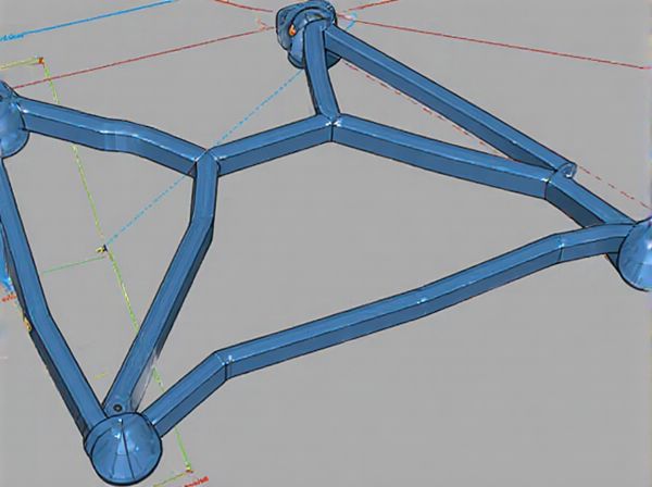
Photo illustration: Parallelogram Linkage vs Triangular Linkage
Parallelogram linkage offers superior stability and uniform motion, making it ideal for applications requiring consistent mechanical movement. Triangular linkage provides rigidity and strength with fewer components, suitable for structures needing high load-bearing capacity. Your choice depends on whether smooth motion or structural strength is the priority.
Table of Comparison
| Feature | Parallelogram Linkage | Triangular Linkage |
|---|---|---|
| Design Type | Four-bar parallelogram mechanism | Three-bar triangular mechanism |
| Steering Precision | High accuracy with minimal play | Good accuracy but slightly less precise |
| Durability | Robust under heavy loads | Moderate durability, suitable for lighter vehicles |
| Complexity | More complex geometry and assembly | Simpler mechanical design |
| Cost | Higher manufacturing cost | Lower cost and easier maintenance |
| Common Applications | Passenger cars, trucks requiring stability | Light vehicles, go-karts, and small cars |
Introduction to Mechanical Linkages
Parallelogram linkages consist of four rigid bars connected to form a parallelogram, allowing for parallel motion and precise angular displacement control in mechanical systems. Triangular linkages, often comprising three bars forming a triangle, provide greater structural rigidity and are commonly used to maintain fixed angles or create stable support structures. Both types are fundamental in mechanical linkage design, enabling controlled movement and force transmission in machinery such as robots, engines, and automation systems.
Overview of Parallelogram Linkage
Parallelogram linkage consists of four bars forming a parallelogram shape, allowing one side to mirror the motion of the opposite side with precise angular control. This mechanism maintains parallelism throughout its movement, providing consistent orientation and smooth, linear motion in applications such as robotic arms and mechanical linkages. Compared to triangular linkage, parallelogram linkage offers enhanced stability and uniform motion, making it ideal for tasks requiring synchronized movement and accurate positioning.
Overview of Triangular Linkage
Triangular linkage consists of three rigid bars connected to form a triangle, providing inherent structural stability and preventing shape deformation under load. This configuration offers precise motion control and increased rigidity compared to parallelogram linkages, which typically have four bars and allow for more flexible movement but less stability. Engineers often prefer triangular linkages in applications requiring exact positioning and minimal deflection, such as robotic arms and precision instruments.
Structural Differences
Parallelogram linkages consist of four bars connected to form a quadrilateral, maintaining parallel opposite sides which allow for consistent angular motion and planar stability. Triangular linkages are composed of three bars forming a rigid triangle, providing enhanced structural rigidity and resistance to deformation under load. The key structural difference lies in the parallelogram's ability to flex while maintaining parallelism, contrasting with the triangular linkage's inherent geometric stability and fixed shape.
Motion and Range Capabilities
Parallelogram linkages provide consistent angular movement and maintain orientation of the connected components, offering smoother and more predictable motion paths ideal for applications requiring parallel motion. Triangular linkages deliver greater structural rigidity and stability, enabling a wider range of motion with enhanced load-bearing capabilities, often used where complex pivoting or variable angles are necessary. The choice between parallelogram and triangular linkages depends on the required precision of motion and the extent of angular displacement needed in mechanical systems.
Strengths and Weaknesses
Parallelogram linkages offer consistent angular motion and maintain parallelism between opposite links, making them ideal for applications requiring precise linear displacement and stability under load. Their weakness lies in lower structural rigidity compared to triangular linkages, which can lead to deformation under high stress. Triangular linkages provide superior strength and rigidity due to their fixed geometrical shape, effectively distributing forces and resisting deformation, but they are less capable of maintaining constant orientation, limiting their use in applications needing parallel movement.
Typical Applications in Engineering
Parallelogram linkages are commonly used in applications requiring consistent angular orientation, such as robotic arms and suspension systems, where maintaining parallel motion is critical. Triangular linkages are preferred in mechanisms demanding structural rigidity and load distribution, like bridges and crane supports, due to their inherent geometric stability. Both linkage types are essential in mechanical design for optimizing motion control and load management in various engineering fields.
Stability and Load Distribution
Parallelogram linkages provide enhanced stability due to their ability to maintain parallelism between opposite sides under load, which evenly distributes forces across all joints, reducing stress concentrations. Triangular linkages offer superior rigidity as their fixed angles prevent deformation, ensuring efficient load transfer primarily through axial forces in members. In applications demanding consistent alignment and balanced load sharing, parallelogram linkages excel, while triangular linkages are preferred for structures requiring maximum stiffness and minimal deflection.
Maintenance and Longevity
Parallelogram linkages generally require less maintenance due to their symmetric load distribution, which reduces wear on individual joints and extends component lifespan. Triangular linkages, while structurally rigid, often experience higher stress at connection points, necessitating more frequent inspections and replacements. Proper lubrication and alignment checks are critical for both systems to maximize longevity, but parallelogram designs typically offer greater durability in high-cycle applications.
Choosing the Right Linkage for Your Project
Selecting the right linkage for your project depends on the specific motion requirements and load distribution; parallelogram linkages provide consistent angular motion and are ideal for applications needing precise parallel movement, while triangular linkages offer greater rigidity and stability under varying loads due to their geometric strength. Consider the complexity and space constraints of your design, as parallelogram linkages often allow for simpler, more compact mechanisms, whereas triangular linkages can handle heavier loads with enhanced structural integrity. Material properties and cost-effectiveness should also factor into your decision, ensuring optimal performance and durability in the final application.
 caratoz.com